
From inspection to evidence: six stages
Identify manual and cover type
Plan safety and isolation
Inspect interacting components
Define suitable test and scope
Correct defects and verify again
Complete records and authorised acceptance
Four system inspection areas
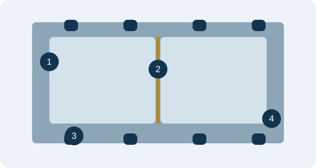
Perimeter seal
Gasket and mating surface.
Panel joint
Cross-joint, seal and drainage.
Support and securing
Pads, alignment and cleats.
Drainage and operation
Channels/outlets and operating components.
Identify the cover and its manual first
Identify type, maker/model, panel numbers and the ship-specific drawings. Obtain operating sequence, movement limits, load restrictions, lubrication, renewal criteria and adjustment values from the maker manual. Request missing documents from the technical office/maker; do not transfer another ship’s settings.
Control movement and stored energy
Use the SMS to establish control authority, visibility/communications and exclusion zones. Clear the movement envelope; secure open covers with their designed mechanical safety devices. Before maintenance isolate electrical/hydraulic energy, manage stored energy by the approved procedure and verify isolation. Never rely solely on hydraulic pressure beneath a cover or search for pressure leaks by hand.
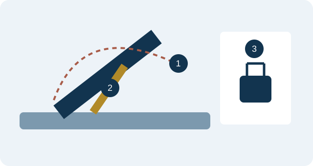
Original technical illustrations, not vessel photographs or acceptance standards. Numbers are explained below.
Visual field guide
Movement envelope and mechanical securing
- 1 · Movement envelope: personnel and obstructions clear.
- 2 · Designed open-position securing: verified in place.
- 3 · Isolation: energy and restart controls before maintenance.
This is not an operating sequence; locks/supports are cover-specific.
Inspect panels, bearing pads and alignment together
Inspect cracking, distortion, wear, panel alignment, bearing pads, locators/stoppers and connections. Support wear can alter gasket compression. Tightening cleats does not repair faulty steel geometry. Plan welding, shimming, profile changes and structural repairs with the technical office/maker and class where required.
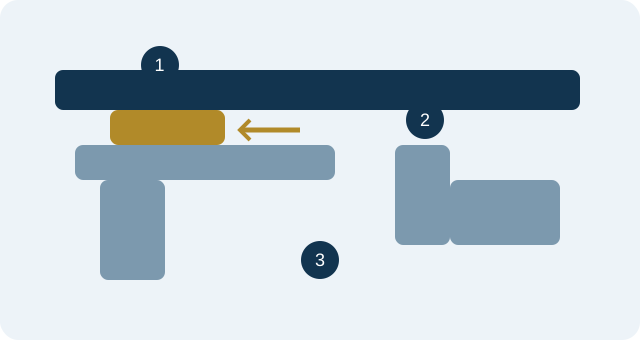
Original technical illustrations, not vessel photographs or acceptance standards. Numbers are explained below.
Visual field guide
Support wear also changes compression
- 1 · Panel/bearing pad: load path and position.
- 2 · Locator/stopper: designed movement restraint.
- 3 · Alignment/clearances: measure to maker drawings.
Gold arrows identify inspection areas, not tolerances. Do not compensate by extra cleat tightening.
Check gaskets, mating surfaces and securing
Record cuts, hardening, permanent set, detachment, corner/joint defects and off-centre imprints. Match profile, material, adhesive and design compression to the exact system. Do not paint seals or choose lubricant without maker approval. New rubber alone cannot correct faulty supports, alignment or mating surfaces.
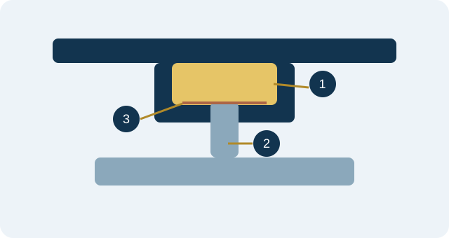
Original technical illustrations, not vessel photographs or acceptance standards. Numbers are explained below.
Visual field guide
Match gasket and mating surface
- 1 · Gasket/retainer: correct profile and secure attachment.
- 2 · Mating surface: damage, corrosion and alignment.
- 3 · Contact imprint: position/continuity, not proof of tightness.
Generic conventional gasket/compression-bar schematic only; not all covers use this seal arrangement.
Trace the full drainage path
Inspect perimeter/cross-joint channels, outlets and designed non-return valves. Record cargo, rust, paint and blockage; do not alter the design by removing valve elements or adding improvised hoses. Verify flow/function after cleaning using the vessel procedure.

Original technical illustrations, not vessel photographs or acceptance standards. Numbers are explained below.
Visual field guide
Preserve the drainage barrier
- 1 · Designed water collection channel.
- 2 · Outlet/non-return valve: inspect blockage/damage.
- 3 · Hold side: water must not reach cargo.
Arrows illustrate flow only. Verify valve type/outlet route from ship drawings.
Inspect hydraulic and mechanical operation
Check hoses, connections, cylinders, chains/wires, wheels, hinges and safety devices as applicable. Record leakage, damage, corrosion, unusual movement/noise or binding. Stop on abnormal movement; do not guess pressure, relief-valve or chain adjustments. Verify oil and intervals from manual/PMS.

Original technical illustrations, not vessel photographs or acceptance standards. Numbers are explained below.
Visual field guide
Record leakage and irregular movement
- 1 · Power/control unit and isolation points.
- 2 · Hose, connection and cylinder: safe visual inspection.
- 3 · Wheel/track/hinge: obstructions, wear and coordinated movement.
Schematic system; not all covers are hydraulic. Never find pressure leaks by hand.
Distinguish contact checks from tightness testing
Chalk marks indicate contact; alone they prove neither design compression nor tightness. Define hose/ultrasonic scope, conditions and acceptance through the method/equipment, maker, class and assignment requirements. Use competent operators, suitable equipment and traceable reports; do not issue a blanket acceptance from one reading or an unexplained percentage.

Original technical illustrations, not vessel photographs or acceptance standards. Numbers are explained below.
Visual field guide
Ultrasonic testing needs location and reference
- 1 · Suitable emitter placement and method reference reading.
- 2 · Joint scanning by a competent operator.
- 3 · Leak map, readings and acceptance basis in the report.
Not an equipment operating instruction. Frequency, units and thresholds depend on equipment/method.
Three methods, different evidence
| Method | What it shows | Limit / requirement | Report evidence |
|---|---|---|---|
| Chalk / contact check | Shows contact between gasket and mating surface. | Does not prove design compression or tightness. | Imprint, position, discontinuities and method. |
| Hose test | Investigates water ingress under test conditions. | Assess cargo wetting, temperature/access restrictions; obtain parameters from the applicable procedure. | Scope, conditions, method parameters, observation locations and result. |
| Ultrasonic test | Investigates leakage paths along joints. | Requires competence, suitable equipment, reference reading and defined acceptance basis. | Operator/equipment identity, reference, settings, readings, leak map and retest. |
A pass must be read with scope, conditions and acceptance criteria. This table is not an equipment instruction or certification. Gard — testing guidance ↗
Correct the defect and verify the same location
Identify each defect by hatch-panel-side reference. Assign responsibility, target date, spares and specialist/class attendance where required. After repair recheck affected system components and tightness by the appropriate method. Tape, foam or filler is not a substitute for correcting defects, technical acceptance or required testing.
Verify closure after loading and before departure
Confirm hatch tops, tracks, mating surfaces and drains are clear of cargo/obstructions. Follow the maker closing/securing sequence; verify every panel and securing device. Include access hatches and related openings. Report known defects to the master/technical office; operational/voyage decisions require authorised assessment.

Original technical illustrations, not vessel photographs or acceptance standards. Numbers are explained below.
Visual field guide
Every panel and securing point
- 1 · Perimeter/cross-joints: residue and obstruction check.
- 2 · Securing points: verify each closure.
- 3 · Access/other openings: included in the closure plan.
Generic plan view; obtain actual securing count, location and sequence from the manual.
Link PMS, test and photographic records
Keep inspection time/place, hatch/panel, finding, method, reference document, photos, correction and retest result together. Before/after images must identify the same location. Test reports should trace operator, equipment, settings/reference readings and acceptance basis. This guide is not a certificate or class report.
FINDING → REVIEW → VERIFICATION
Common onboard situations
New gasket fitted; leakage remains
Review profile/joints together with supports, panel alignment and mating surface. Do not compensate with extra tightening or improvised backing. Record location and obtain technical-office/maker assessment.
Channel looks clean; water still collects
Check the remaining route, outlet and designed non-return valve. Do not remove components to change the system; arrange controlled functional verification under vessel procedures.
Panel binds or moves irregularly
Stop, secure the area and maintain control authority. Have authorised personnel assess loads/obstructions, tracks/wheels/hinges and power system. Do not force movement by increasing force/pressure.
Ultrasonic report says only “OK”
Request operator/equipment identity, reference reading, scanned areas, readings, method/acceptance basis and defect map. A non-traceable result does not complete the assessment.
TECHNICAL READING AND TRAINING
Choose the document for the task
IMCS / AMVP
Why the manual matters
A short inspection note explaining why a missing manual undermines maintenance and repairs.
Open official note ↗UK P&I / IMCS
System and inspection
Technical reading connecting components, maintenance, testing and evidence.
Risk Focus: Hatch Covers ↗IMCS TRAINING ACADEMY
Practical training
Official programme information for hatch-cover maintenance/repair and ultrasonic-test competence.
Hatch Covers — Masterclass ↗SDT / IMCS — Level 1 ↗Independent source links; they do not imply endorsement of our company or this guide. Verify training details with the provider. Third-party photographs/drawings have not been copied.
Downloadable hatch-cover checklist
3 pages · 24 checks · Record fields for printing and completion. A general reference form, not a replacement for a company-approved SMS form.
Download checklist (PDF) ↓Practical questions for masters
Does continuous chalk mark mean the test passed?
No. Contact marks do not prove tightness or design compression. Required testing and acceptance remain separate.
Should cleats simply be tightened more to stop a leak?
Investigate gasket, supports, alignment and mating surface first. Authorised adjustment uses maker values; overtightening is not a repair.
Can the same grease be used on all seals?
No. Confirm material/profile/mating-surface compatibility with the maker. Do not use paint, arbitrary petroleum products or generic adhesive.
Can a hose test be done over loaded cargo?
Do not expose cargo to wetting. MacGregor guidance specifies empty holds. Select the appropriate method for the assignment/conditions; ultrasonic testing also requires competence and procedure.
Is tape or foam sufficient to close a leakage defect?
It does not replace repair or required testing. Additional sealing products require appropriate assessment; hiding the defect is not acceptance.
Does one ultrasonic percentage apply to every test?
No. Specify equipment, reference reading, units, method and applicable criteria together. Do not detach a percentage from its context.
Product and vessel documents
Compare with the vessel maker/model and approved drawings. Verify dimensions, settings, lubricants, test acceptance and repairs from ship-specific documents.
Technical sources
- IMCS — Hatch cover manual: AMVP inspection note
- IMCS Training Academy — Hatch Covers Masterclass
- IMCS / SDT — Ultrasonic hatch cover testing training
- UK P&I Club / IMCS — Risk Focus: Hatch Covers
- MacGregor — Sealing solutions (November 2025)
- The Swedish Club — Wet Damage on Bulk Carriers
- Gard — Are your hatch covers weathertight?
- London P&I Club — Holds and hatch covers